Which of the following diagram correctly represents the state of stress at a point above the neutral axis of the cantilever beam with uniformly distributed load with intensity “q”?
- A
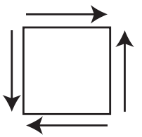 Correct
- B
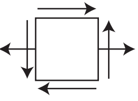
- C
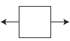
- D
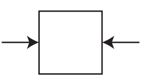
Solution
Concept
State of Stress in Cantilever Beams
Formula
σ = My / I and τ = VQ / Ib
Step-by-step solution
1. Identify hogging bending moment causing horizontal tensile stress above the neutral axis using σ = My / I. 2. Determine transverse shear stress acting on the element using τ = VQ / Ib. 3. Combine tensile normal stress and shear stress components to select the matching stress element diagram (Option A).
Explanation
For a cantilever beam subjected to a downward load, the beam undergoes hogging (bending upwards). This creates tensile (pulling) normal stress in the region above the neutral axis. Therefore, a stress element located above the neutral axis experiences horizontal tension along with shear stress caused by the transverse load. Option A correctly represents this tensile normal stress and corresponding shear stress state.
Shortcut
Cantilever beam with downward loading undergoes hogging (bends upward): - Above Neutral Axis (Top) = Tension (+σ) - Below Neutral Axis (Bottom) = Compression (-σ)Shortcut: Top = Tension, Bottom = Blocked/Compressed.
Common mistake
Many students mistakenly apply the bending behavior of a simply supported beam (where the top fiber is in compression) instead of a cantilever beam (where hogging causes tension above the neutral axis), leading them to incorrectly select a compressive stress diagram.
Correct answer: A)